Easy Way to Build a Lithium Ion Battery Charger
The submit describes an easy lithium polymer battery with more than charge cut off function.
A Lithium polymer battery or perhaps a lipo battery is an innovative breed of the widely used lithium ion battery, and exactly like it's older counterpart is specific with stringent charging and discharging parameters.
In spite of this if look at the these specs in detail we come across it to be rather lenient as much as the prices are involved, to become more accurate a Lipo battery may be imposed at the rate of 5C and produced even at lot more rates, here "C" is the AH rating of the battery.
The above specifications in fact provides us the liberty of utilizing lot more current inputs without stressing about an over current circumstance for the battery, which can be usually the case when lead acid batteries are needed.
It implies the amp rating of the input could possibly be overlooked in many instances considering that the rating may well not surpass the 5 x AH spec of the battery, generally. With that in mind, it's always a much better and a secure idea to charge such important devices with a rate that could be lower than the max stipulated level, a C x 1 may very well be the captured as the optimum and the most secure rate of charging.
Considering that right here we have been excited about the charging strategy of a lithium polymer battery, we are going to focus a lot more with this and observe precisely how a lipo battery might be charged safely yet optimally utilizing elements that could be previously sitting in your electronic junk box.
Talking about the demonstrated diagram, the whole design could possibly be observed set up around the IC LM317 that may be generally a flexible voltage regulator chip and has all the security benefits integrated. It is going to not permit more than 1.5 amps across it's outputs and guarantees a safe amp level for the battery.
The IC here is fundamentally employed for establishing the precise needed charging voltage level for the lipo battery. This might be achieved by modifying the supported 10k pot or a preset.
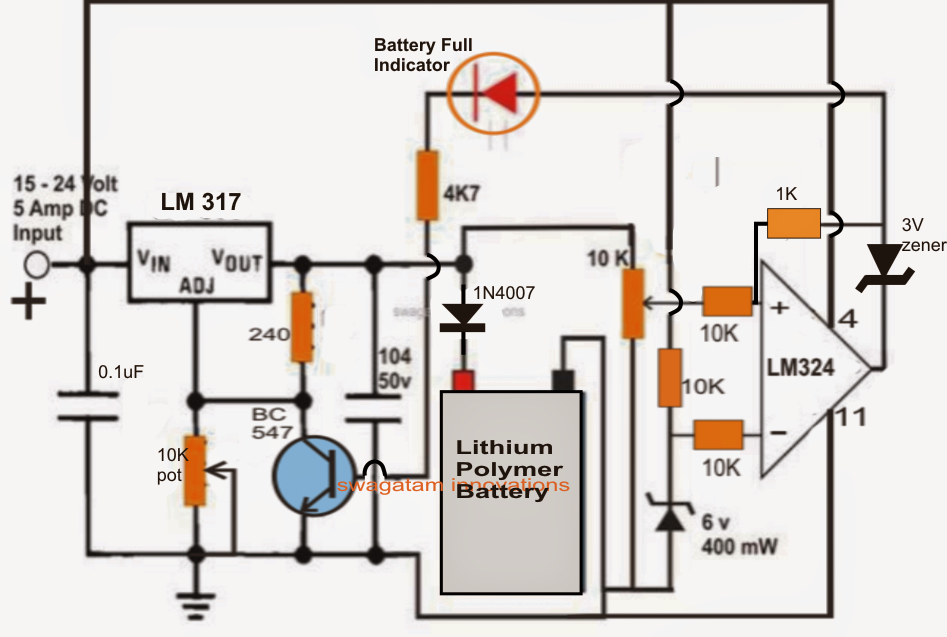
The section at the significant right which includes an opamp is the over charge cut off stage and ensures that the battery is rarely permitted to overcharge, and cuts off the supply to the battery the moment the over charge threshold is attained.
The 10 k preset placed at pin3 of the opamp is utilized for setting the over charge level, for a 3.7 V li-polymer battery this might be set such that the output of the opamp goes high whenever the battery is charged to 4.2 V (for a single cell). Since a diode is located at the positive of the battery, the LM 317 output needs to be set to about 4.2 + 0.6 = 4.8 V (for a single cell) for compensating the followed diode forward voltage drop. For 3 cells in series, this value will have to be modified to 4.2 x 3 + 0.6 = 13.2 V
When power is very first turned on (this ought to be completed after hooking up the battery across the presented position), the battery being in a discharged state pulls the supply from the LM317 to the current level of its voltage level, let's believe it to be 3.6 V.
The above circumstance retains pin3 of the opamp well below the reference voltage level fixed at pin2 of the IC, producing a low logic at pin6 or the output of the IC.
Right now as the battery starts building up charge its voltage level begins rising until it attains the 4.2 V mark which pulls pin3 potential of the opamp beyond pin2 forcing the IC's output to go immediately high or at the supply level.
The above encourages the indicator LED to light up turn on the BC547 transistor attached across the ADJ pin pf the LM 317.
As soon as this occurs the ADJ pin of the LM 317 receives grounded forcing it to turn off its output supply to the lipo battery.
On the other hand at this moment the complete circuit becomes latched in this cut off position as a result of the feedback voltage to pin3 of the opamp via the 1K resistor. This procedure guarantees that the battery under no situation is able to obtain the charging voltage once the over charge limit is achieved.
The circumstances remains locked until the method is turned OFF and reset for likely beginning a new charging cycle.
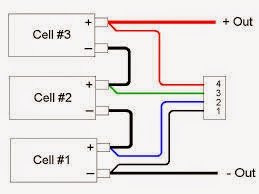
In the above recommended 11.1V battery pack, there are 3 cells in series and the battery poles are shut down separately by means of a connector.
It's suggested to charge the individual batteries separately by spotting the poles properly from the connector. The diagram demonstrates the simple wiring information of the cells with the connector:
Reader Interactions
Source: https://makingcircuits.com/blog/lithium-polymer-battery-charger-circuit/
0 Response to "Easy Way to Build a Lithium Ion Battery Charger"
Post a Comment